
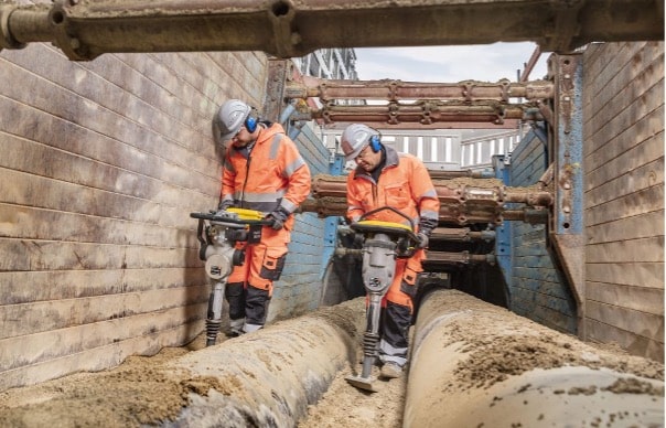
It’s a common occurrence to see pavements settle and create a traffic hazard where trench works have been completed across a road, particularly when these trenches are installed after the original road pavement is constructed. Settlement typically occurs for two reasons:
- Backfill material selection
- Compaction
In this article, we focus on compaction only. Aside from backfill material issues, poor compaction typically occurs due to a lack of adequate compaction of the trench backfill or the inability to test the backfilling for compaction real time during the construction process and give real time feedback of compaction progress.
Trench Terminology
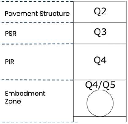
The Embedment Zone is the area around a pipe between the foundation, the trench or embankment fill and the trench walls. Embedment includes bedding, side support, haunch support and overlay.
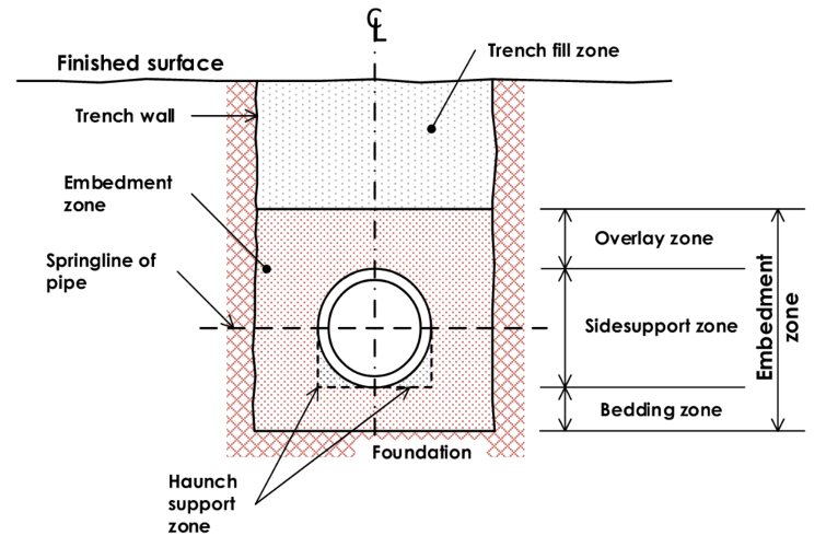
Figure 1: Terminology of buried flexible pipelines (Source: SA Waters – TS 0631 Rev 2.0) in accordance with AS 2566.1.
Why is the Trench Backfilling Process Important?
From a civil engineering perspective, we must adequately embed and compact material around the buried pipeline and culverts to resist vertical loads (e.g. loads due to the weight of the backfill and vehicle traffic) without excessive deformation of the pipe or culvert and the finished ground.
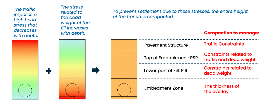
Figure 2 – Stress Balance on a Trench
If we don’t apply appropriate compaction, the pipe or culvert will get squashed down vertically and bulged out sideways when loaded with trench fill and traffic.
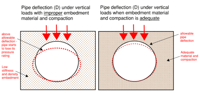
Figure 3 – Pipe Deflection Under Load – Improper Vs Adequate Embedment
Manufacturers usually design flexible pipes assuming that the embedment will be stiff enough to limit the vertical deflection of the pipe. If this deflection is exceeded, then the combined stress in the pipe walls from the oval shape and internal pressure will exceed the design stress, and the life of the pipe will be shortened.
Placement and Compaction of the Embedment Zone
The embedment material must provide the required support for the pipe or culvert, but the compaction process must not put the pipe or culvert out of round. The most important place for a good compaction to be achieved is generally in the side support zone and particularly in the haunch support zone of the pipe. Refer to Figure 1.
Figure 4 illustrates why side support must be uniform and the material placed and compacted in lifts.
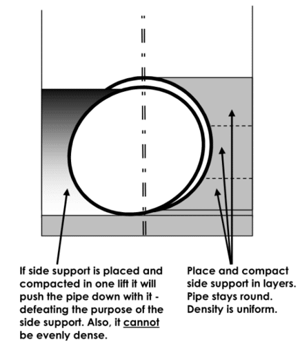
Figure 4 – Illustration showing why side support must be uniform and packed in lifts (Source TG 0637 – General Technical Information for Geotechnical Design – Pipelines, SA Water)

To compact the embedment zone, the following placement and compaction requirements should be followed:
- Hand tampers or vibratory tamping rammers can be used for embedment compaction.
- The side support and overlay material shall be placed in layers of appropriate thickness for the method of compaction, to achieve the specified relative compaction (density) or soil modulus.
- The pipe overlay material should not be placed until the pipe side support material has been placed and compacted.
- Compaction of embedment material directly above the pipe in the overlay zone shall not commence until the total depth of fill material above the top of the pipe is at least 100 – 300 mm, depending on the diameter of the pipe or culvert.
Compaction and Traditional Testing of the Trench Fill Zone
For example, in Victoria (Australia), the trench fill zone (refer to Figure 1) of a service trench is generally completed in a two part process.
- Lower Layer (from 300 mm above pipe/conduit/culvert to 600 mm below the surface).
- Upper Layer (from 600 mm below to the surface)
The Lower Layer of material is typically compacted and the trench stays open until it is tested for compaction using a Nuclear Density Meter. The test results typically take, at minimum, 1-2 days to complete with a NATA accredited testing facility who are licenced to operate the Nuclear Density Meter (NDM) equipment.
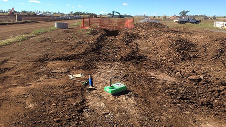
Then the Upper Layer of backfill material is placed in layers and compacted.
Finally, the wearing course, a temporary asphalt cap (cold mix), is applied and the road is opened to traffic again. Typically, a few days later, another density test to measure the level of compaction at the top of the Upper Layer is carried out. Traffic management is required. The results come back a few days after this.
If it passes, some days or weeks later, the asphalting crew come by and apply a hot mix asphalt cap to the trench. Again traffic management is required.
Challenges with the Traditional Compaction Control techniques
In Australia, New Zealand and the rest of the Pacific Region, the most commonly used methods for compaction control of trench backfill are Nuclear Density Measurement and Sand Replacement Testing. The main issues with these methods are:
- nuclear densometers don’t perform too well in trenches because of back scatter and feedback takes at least 1-2 days.
- sandreplacement method is time consuming and very prone to errors in the hands of an unexperienced technician.
- having compaction testing capability available when you need it and providing immediate feedback to the construction crew.
- compaction testing depth typically limited to 300mm depth
Testing Trench Compaction in Europe and now in Australia and New Zealand
We are seeing a progressive change from the traditional compaction control approaches, with a focus on providing close to real time feedback during the compaction process, delivering a better quality outcome with an increased level of confidence.
Light Weight Deflectometer
In Europe and elsewhere, the process is very different to the traditional compaction control approaches commonly used in the Pacific region. Pavements are typically designed using modulus, it being the most accurate and independent means for judging deformation (stiffness) and, thus, a material’s level of compaction.
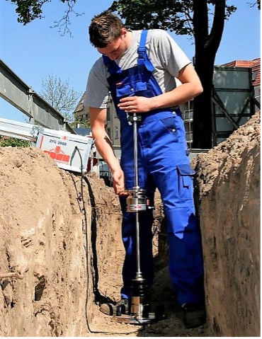
In Germany, for example, prior to beginning the trenching process, the asphalt is removed and an assessment is made of the modulus of the Upper Layer. Typically, this is done using a Light Weight Deflectometer (LWD), a layer by layer compaction control tool. The Light Weight Deflectometer is used to determine the stiffness of unbound materials (subgrade/subsoils and base layers, granular layers & backfilling materials) or partially bound material (e.g. stabilised) during construction or rehabilitation works. It’s repeatable, fast (test is done in 3 minutes) and gives you immediate GPS located results.
The trenching process now begins. When it comes to backfilling, each layer is compacted and then tested using the Light Weight Deflectometer. The depth of influence of the Light Weight Deflectometer test is almost twice as much as the Nuclear Density Gauge method.
To avoid unwanted settlements, compaction has to be tested and results documented for every material layer by the contractor in a mandatory self-monitoring process. Target values for modulus measurements for different subgrade layers and standard construction materials can be found in the respective German design guidelines such as the “ZTV A-StB” or the “RStO”. These guidelines furthermore recommend a minimum number of passes for different compaction equipment for all layers of construction.
Once the Upper Layer is compacted, a final test is done using the Light Weight Deflectometer. The result achieved should be the same or a higher level of modulus, compared to the original modulus value taken prior to the trenching process starting.
The industry body, Güteschutz Kanalbau e.V. have created an excellent step by step interactive video and animated guide for the process.
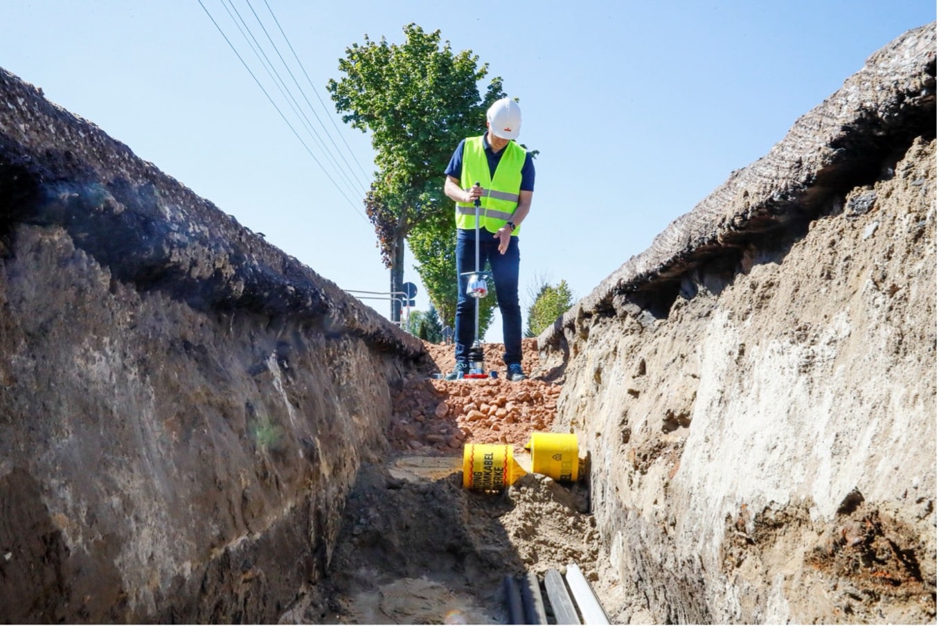
This trenching and backfilling process is much faster and overcomes the shortcomings of the traditional Nuclear Densometer approach. In Australia, we have seen the Light Weight Deflectometer (LWD) layer by layer compaction control approach for trench bedding layer, embedment zone and backfill being applied to gas, sewer and water pipelines, as well as culverts and service conduits.
PANDA® Variable Energy Dynamic Cone Penetrometer - Variable Energy Dynamic Penetrometer (VEDP)
In France, trench backfilling and compaction is ruled by a technical document issued by the transportation ministry. According to the location of the trench, compaction specifications vary. Compaction targets are expressed in terms of density as a percentage of the Proctor Optimum.
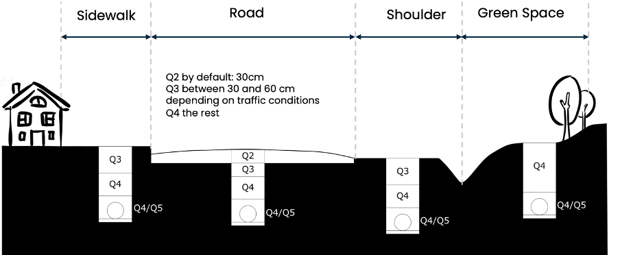
The guide provides a table specifying the thickness of the layers as a function of the compaction requirements, soil classification and type of compactor.

In terms of compaction quality assurance, to have a just and impartial assessment, public authorities generally require independent verification carried out by an accredited laboratory.
They would usually demand the use of standardized dynamic penetration tests, one of which is the PANDA® Variable Energy DCP, which is not subject to the layer thickness limitations typical of other devices.
The PANDA®, a Variable Energy Dynamic Penetrometer (VEDP), enables you to test through multiple layers at the same time so you can check uniformity of compaction, layer thickness and performance to specification. It’s light, very portable and we can even have the compaction specification plotted on the hand held terminal so the person testing can see straight away where they are at in relation to the specification. You can also use it beyond trench backfill applications.
The interpretation of the conformity of the test is quite simple and is detailed in the standard NF 94-105. The conformity algorithm is embedded in the PANDA® WebSprint© software which make it an automatic hassle-free process.
In terms of protocol, the general policy is to carry out a test on all the backfilled trench layers at once when the work is complete. It saves time and money compared to the layer by layer control, which would also be technically possible with the PANDA®.
This strategy of independent control at the end has raised the awareness of the contractors regarding the compaction process and all control laboratories have noticed a significant improvement in terms of quality during the last ten years.
In Australia, we have seen the PANDA® Variable Energy DCP compaction control approach for trench bedding layer, embedment zone and backfill being applied to sewer and water pipelines, as well as culverts.

Case Study - Culvert Replacement with PANDA Compaction Control
Part of the Snowy Hydro 2.0 early works project involved the installation of new culverts as part of the upgrade of bush tracks for construction vehicles. Whilst new culverts were being installed, the internal road would be closed to all traffic. Hence, speed of construction was a key factor.
Conventional Approach
The traditional Transport for NSW (TfNSW) compaction specification required each 200mm backfill layer to be tested for compaction (both field density and a laboratory test). Each laboratory test required both laboratory compaction and a moisture content assessment. In general, there were 5 lifts. Hence a total of 15 tests were required for each location with 5 return trips required by the geotech.
Alternative Approach
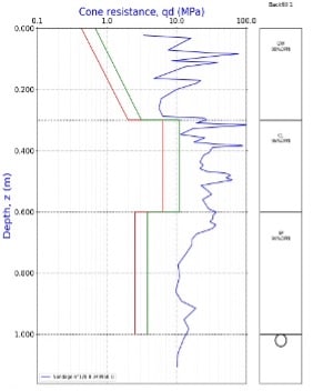
Construction proceeded with multiple lifts of material placed and compacted in quick succession. Then, in a single test, the PANDA Variable Energy DCP was used to assess the cone resistance through the material (through multiple layers of backfill, through the haunch and into the bedding support), and this was related to the Compaction Control database that relates density and cone resistance. This method leaned on the French approach to trench backfill contained in NF P 94 105. The layer depth, uniformity and compaction achieved for each layer was able to be assessed.
Finally, compaction was assessed in the traditional way at the surface, with Nuclear Density Gauge and Lab compactions.
Hence a total of 4 tests were required for each location for compaction purposes and only one return trip was required by the geotech.
The use of the PANDA® compaction control method in this project demonstrated a more efficient and cost-effective approach to culvert backfill testing. By reducing the number of tests and site visits without compromising compaction quality, the method accelerated construction timelines and minimised road closures. This case study highlights the potential for adopting innovative, standards-backed alternatives to traditional compaction testing in similar infrastructure projects.
Conclusion
Ensuring proper compaction in pipeline trenches and around culverts is vital to the long-term performance and safety of infrastructure. Traditional compaction testing methods, while widely used, often fall short in efficiency and accuracy. Modern approaches like the Light Weight Deflectometer and PANDA® Dynamic Cone Penetrometer offer real-time, layer-by-layer assessment, enabling faster construction and more reliable results. These tools empower engineers and contractors to make informed decisions on-site, reduce delays, and improve construction quality. Embracing these innovative technologies will lead to more sustainable, cost-effective, and resilient infrastructure solutions across Australia, New Zealand, and the wider Pacific region.
If you want to explore these valuable approaches to assess compaction in pipeline or cable trenches and around culverts, let’s have a conversation.

